Sunday, 17 February 2013

Layup and curing Wing component (wing test)

The component is produced with wet layup in a similar fashion as the molds  The difficulty with wet layup is that the low resin viscosity and low tack makes it hard to preform and assemble. The plies were cut using paper templates created directly from CATIA v5. A drappability analysis was conducted on each layer to define the cutting kits.

Standard 2x2T 200 gsm was used with 5 layers on each wall. The spars have 4 layers each of the same material. Resin is Axson Epolam 2022, and was cured at 60ºC. This cure cycle was selected since this is a test wing to validate the processing, not the structural performance of the wing itself. The Epolam 2022 resin system can be postcured at 100ºC to obtain a higher Tg.


To create the assembly, the material is layup on each upper and lower moulds, including cores. After that, the spar preforms are layup on the mandrels and foam cores. Each preform is bagged and debulked separatelly before being assembled.


The end result was quite good and showed that wet layup could be used for the entire car. However, weight is such a big concern that it will have to be studied a bit further with different parts and perhaps compare that with a prepreg-alike made. For a wet layup I expect a 20% more RW than for the prepreg, but on the other hand is so much cheaper.

I am planning on making a simple sample test plan to obtain material characteristics for the FEA. Even though I do not have FEA software to compute dedicated composite elements, a shell analysis with a definition of the orthotropic properties for each type of laminate area would do. I will use the rule of mixtures to combine the different layups and materials.

Saturday, 16 February 2013

Inserts and core making (wing Test)

Inside the wing there are several inserts, cores, foam cores and a mandrel, which will be used to make the component. Only the inserts and core will remain in the finished part. After the cure, the silicone mandrel is extracted and the foam cores destroyed.


Since there are different materials, each one has a different manufacturing process. Here is the way to manufacture them:
Foam cores: Foam is usually machined because of the shapes it is designed for. Machining foam is not a big deal, but the fixing of it might be. Because the foam cores for the wing are machined all around, I designed a vacuum tool for one of them. The other two are machined into a big foam core and them cut with a staler knife.


Core trimming: The cores are made out of balsa wood for the test. I am planning to use structural foam such as Rohacell and honeycomb for the actual car. The thickness of the core is 1.5 mm so I used a skimmed 2mm balsa sheet. I trimmed it using paper templates and chamfer it with a knife and chisells.

I used an interesting techique  to curve the balsa wood which consists in wetting the side of the wood which will become the convex surface. I used a bottle with a nozel to get a uniform water layer. After 10 minutes, the balsa wood has absorbed the water and bends by itself. At this point I placed the cores on the mould in the right position and bagged them in vacuum. Then baked them for  90 minutes at 60ºC and cool down slowly under vacuum, with a release below 30ºC. With this process the curvature on the balsa becomes permanent. The alignment of the balsa natural fibre has to be in the direction of the bending axis. I did not tried to do it in the other direction so it might work as well but I guess it will be harder.


CFRP inserts:  To connect the wing with bolts and other fixing elements, CFRP are embedded inside the structure. CF is used because it is light and has good strengh to hold a metallic insert such as a dowel or keensert. The drilling direction for the metallic element, will be allways perpendicular to the CF layup plane. The layup is usually made with a high gsm fibre and with a QI (Quasi Isotropic) layer orientation. Since the longest insert of the wing is 16 mm, I produced a brick of CFRP of 19 mm (80 layers of 200gsm). I did not have higher gsm fibre so there you go...

The insert drilling is made after curing the component in the curing tool. The curing tool is used as well for the drilling.


Silicone mandrel: The silicone mandrel is used to apply internal pressure to the spar area during the cure cycle. The difference in CTE between the CFRP mould and the silicone means that the silicone will expand and squeze the laminate against the rigid mould.
The silicone I used is a ESSIL 20 from Axson. It is a bicomponent produce that can be poured into a cavity. It cures at RT in 7 days, but can be released after 24h.


The inserts in the tool cavity look like this:


Wing Test Mould building

Because I had holidays for quite a few days during Christmas, I have been able to work a lot on the wing. Of course, the tooling part of the project is the longest, especially because the wing is cocured. This requires the tooling to incorporate mandrels in different materials to be able to obtain the entire part in one cure cycle. In addition, the mandrels have to be removed without damaging the part.

Since I have no autoclave available, a silicone mandrel will produce the pressure inside the wing structure during the cure. The design and processing of the wing is the same as for a real part, except I cannot use tubular vacuum bags in some cavities due to its size. Therefore, the pressure has to be created inside the cavities so it either has to be a rigid-removable mandrel or expansible mandrel.

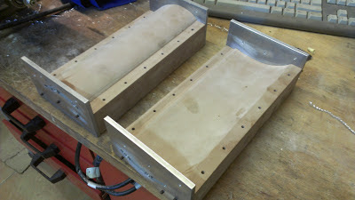
Basically, I produced the patterns, composite tooling, silicone mandrel, and some of the foam cores and wooden cores. I used my CNC milling machine to make them all, which is quite a pleasant compared to my other models which had patterns produced by hand.

As I do want to keep it within a reasonable budget, I did not use prepreg. Instead, I used wet layup for all compsite parts, and will try to do the same for the component as well. Here are the pictures of the wet layup process:


 Both patterns have aluminium side plates to create the verticall wall for the composite tooling. A pair of these plates is used joint the composite tooling for the cure cycle.
The plates also have the drilling guidance holes to drill the CFRP inserts on the actual cured part for mounting onto the endplate.


 This is the impregnated fabric with resin. I used a conventional 2x2T 200gsm with EPOLAM 2022 epoxy resin. The cutting templates are defined in Catia according to the layup sequence and ply contourn. A layer of 80 gsm GF is used on the tooling surface to improve surface finishing.


 This is the fabric being laid-up. It handles well, because it is impregnated feels like a prepreg with a very low resin viscosity. This step is performed on both patterns to obtain the top and bottom wing mould surfaces.

 I made an oven from scratch to cure composite parts, which is really handy. It controls the air temperature only but works wonderfully for such small components. Of course, I use vacuum to compact the parts, as you can tell from the picture.


The mould surfaces are then polished to obtain a better cosmetic finishing on the wing surface. The polishing should be made to 1200 grid.

Thursday, 15 November 2012

Tooling wing test

First tooling parts made from CAD - CAM - CNC on tooling board 600 kg/m3. Easy to machine and good surface finishing. To improve the surface , I will apply body sealer afterwards, before the release agent.


Friday, 19 October 2012

First Composite Parts

Hi all. Following the decision about putting on hold the engine testing, the modelling of the car is started. As a system check, I modelled this wing, following F1 standards. The CATIA model of the rear upper main plain has the intel for composite design of the part: ply pieces, splices, inserts, etc. The structure is quite complex and has Rohacell cores to reinforce the skins, plus two spars running across the wing span. The wing is 1:3 scale, meaning a total span of 252 mm. DXF are produced automatically to cut the plies on prepreg from the CAD model.

Material definition is now still to be defined both for part and tooling. This design and built exercise will prove the manufacturing cycle as well, since will use my Optimum BF20L vario to machine the patterns and final component. The CNC program will be made with Visual Mill based on the solid model created in Catia v5.


Tuesday, 2 October 2012

Time to move on

Even though the IT3 engine is not finished, I decided to put its development on hold. I have changed job and am living away from my home town, in where my workshop is. Hence, I will get started with the design of the car (chassis, composites). This means, there will be some uncertainties about the engine fitting into the whole, but I am sure I can get around it.

I expect the design to be finished somewhere around Oct - Nov 2013. The model and aero surfaces will be finished end of this year. The rest of the detail design will be finished afterwards, including the latest design of the 2013 cars. The particular car to be made will be determined next year, as the newer the car I chose the better it will look when finished in 2015-2016. The engine will be first designed and then the development will continue on the test bench, untill it is running well, recovering the IT3 work. Car manufacturing will start end 2013, along with the engine testing.

Follow me to learn more about the progress with the car design, which looks very exciting! A lot of composite parts to be designed and built! I will try to make some posts about composite manufacturing techniques as it is quite interesting for model making but actually just a few ones use it.

Sunday, 8 July 2012

IT3 test engine preliminary design 2

The preliminary design is almost completed for the 20cc single cylinder test engine. It is expected that specific test components will be produced in the following weeks to assess the design of the cooling and lubrication systems.
The concept designs for the cooling and lubircation system pumps can be seen in the picture below. The final layuot of the pumps will not be incorporated to the engine to reduce complexity. See in green the test water pump. and in purple, the aspirating oil pump. The distribution system uses gears instead of chain, as was used in the previous test engines IT1, IT2. This creates a high degree of complexity during the machinning steps.