Thursday, 19 December 2013

Test engine IT3

After a while of not wrinting any post I finally found a minute to show some pictures of the engine I am working on. This is a single cylinder test engine, which will be used to test the design of the V8 cylinders. The design is almost 100% complete but I have already made some of the main parts.

I will be posting more often from now on. The next two pictures are from the engine head - quite a lot of machining!

These is the engine head rockers bracket. There are two per cylinder. It is quite an original design but I do not think they will make it to the final V8 engine design.

This is the main engine parts put together. The cam cover is missing.

 This is one of the split bearings. It is quite hard to machine due to the tang for locking the position in rotation. It is all made on the milling machine, using a rotary table.It is accurate to 0.01 mm in all dimensions, which is quite an achievement bearing in mind my equipment.
You can see I also do drawings for every single part to keep all the details for when I start designing the V8 engine in a few months.


Monday, 18 February 2013

Dynamic Vehicle Simulation

The last step of the preliminary design is to find out the actual overall performance of the vehicle. For this purpose, I use a MatLab coded 4 corner vehicle simulation, which I developed as my dissertation.

I will not get into much details about the model. In short, it can simulate the forces, accelerations, speeds and travels of each corner of the car, including sprung and unsprung masses. Additionally, it simulates engine and gearbox functions, as well as aerodynamic effects.

After completing the weight estimation and aerodynamic study, the data was input to the MatLab code to simulate a series of maneuvers: pure acceleration, 180º corner and chicane.

Basically, I wanted to find out how the car would perform and if this would be equivalent to the real F1 car.  Let´s take 5g as maximum lateral acceleration of the 1:1 car. At 1:3 scale, this acceleration would be 3 times smaller. Not the force, since there is mass involved, but it would be the acceleration. This is considering, the car has a turn radius of also 3 times less, and speed 3 times less as well. Therfore, the Lat Acc we are looking at is 1,67 g.

In order to run the model, many parameters have to be introduced: polar moment of inertia, masses, inertia of the wheels, engine torque curves, aero parameters, suspension stiffness, and a few more. The CoG is calculated on a quick estimation from the DMU, assuming some masses. The mass is estimated at 12,5 kg, which would be excellent to achieve.

The Tyre model used is a simplified version of Pacejka. The maximum mu coefficient is 2,2, similar to a good racing tyre. I might have gone a bit optimistic here, but the actual values should not be too far. In order to properly find out, I will perform testing on the R26 tyres at 1/5 scale. The tyre construction for this car will be similar.

The simulation is run by a series of driving inputs, that control steering and throttle/brake inputs, as a function of time. After the simulation is run, the results pop up like this:


Therefore, the important results are:
Max Lat Acc: 2,6 g at 120km/h.
Max Long Acc (from a simulation not shown):1,2 g, but average from 15 to 100km/h is 0.56.
Max Speed: 130 ish km/h.

Considering that some of the assumptions might be a bit optimistic, but that there is also room for improvement on the aero side, this results are quite satisfactory. The car will perform slightly better than a scale 1/3 F1 car and will look fast.

Interesting to see from the tyre slip values, is that the handling is very understeering. This is due to the CoP position, which is way too far on the back. I expect to be able to correct this by improving the front wing performance. Testing the simulation with a CoP just 50 mm behind the CoG, an increase of 15% in Lat Acc is obtained.

Next steps is to complete the DMU more components, and perform composite test coupons to gather material data for FEA.

Preliminary design CFD

CFD stands for Computational Fluid Dynamics. To put it in short, CFD are numerical models that are used to study the behavior of fluids within a set of boundary conditions.

As I am building a car at 1/3 scale, it will translate to 1,64 m vehicle in which aerodynamics will play an important role, as it does with the real F1 cars. This is why, for first time in all my cars I have decided to use CFD to improve the aerodynamic efficiency of my car. At this stage, only a preliminary study has been conducted but some valuable data has been obtained. This data will be used in the detail design later on in the project.

The process starts with meshing the geometry to study. The model is the same that was made for the DMU in CATIA, with the difference that I only study the front and rear sections, not the full car. This split is made to save modelling and CPU time.

The model was imported in COSMOS FlowWorks 2007 in iges format. After cleaning the geometry and fixing some defects on the surface, these is what is obtained:

The boundary conditions are stablished as 20 or 30 m/s flow, symetry on the XZ plane and symetry on the XY plane. The latter is used to simulate the road, as a big simplification. I did not want to use rolling floors since it is the preliminary stage only. A real F1 car has about 1500 kg downforce, which translate to 18,5 kg at 1/3 scale. This design is therefore not too far away, considering it still has plenty of room for optimization (assuming a maximum speed of 120km/h which would be 360 km/h on the 1:1 car).

The results were as follows:
FRONT
20m/s: 12.1 N
30m/s: 28.2 N


REAR
20 m/s: 22.7 N
30 m/s: 52.4 N


As you can see, there is flow detachment, especially on the diffuser and front wing airfoils. I am aware this is not correct and should be further developed, but it is just the starting point and a preliminary design.

Drag values were really high, and I assume it is due to not having the full body, rolling floor, and main simplifications on the cooling outlets on the rear section. For the dynamic simulation, a 1/3 of the downforce coefficient is used accounting for the drag.

The rear section, was optimized during several iterations using a NACA profile airfoil. This increased the initial downforce values by around 50%. Further refinements were made to remove airflow separation close to the trailing edge of the RUMP (rear upper main plane) and rear flap.

On the other hand, the front section was not refined, and thus a low downforce value is obtained. Additionally, the front wing is closer to the floor. Therefore the influence of not having a non-rolling floor is more acute than for the rear wing.

The Center of Pressure (CoP) is located -223 mm behind the CoG. This is too far behind, but is the result of the poor front downforce at the moment. The downforce value, might seem low but in fact, comparing it to what should be at 1/3 is not that low. Making some numbers, we find that the downforce is not scaled by 3 times, but by 81 times (F=1/2*p*A*Cz*V^2, area is 3^2 and speed is 3^2, hence 3^4=81). Reynolds number is way within the laminar flow and so turbulent flow is not a concern. 


Sunday, 17 February 2013

Car preliminary design study

After completing the wing test project, I started a preliminary design of the car to overview the estimated performance of the vehicle. I though it was important to make this study at that point, since will indicate me if the car will deliver scale able F1 performance and find out if any other test is necessary on engine, clutch or other areas.

A first iteration of the surface was modeled in CATIA to be used as a DMU (digital mockup). The RB model created is a combined version of the 2010-2013 cars. They all have followed a rather steady evolution, than a revolution. This is why the outer surface has not changed significantly  As always  it is on the details that one can notice the differences.

I started the modelling with the legality box, based on the FIA F1 rules. This model is used to check that the car is within the constrains of the FIA. I used different colors depending on the section of the car.
The next step was to create the surface model of the car body, which means just the outer surface. Only the left section of the car is modeled to save CAD time. The model is then closed to create a solid which is used for the CFD analysis.

 The solid model was split for the front and rear sections. Each model is then independent and transferred into the CFD software.This model is used as well as a digital mock-up. It is used to locate the main components of the car, i.e. chassis, engine, radiators, rc servos, electronics and so on.
Using the generative surface design tools from CATIA the different car sections can be extracted to create separate assemblies. Each assembly is linked to the surface model and any changes to the surface or trimming features are associative to the assemblies.


At this point, the DMU was left on hold, in order to make the CFD analysis, weight estimation and dynamic simulations. With this three steps, an estimation of the performance has been obtained.


Layup and curing Wing component (wing test)

The component is produced with wet layup in a similar fashion as the molds  The difficulty with wet layup is that the low resin viscosity and low tack makes it hard to preform and assemble. The plies were cut using paper templates created directly from CATIA v5. A drappability analysis was conducted on each layer to define the cutting kits.

Standard 2x2T 200 gsm was used with 5 layers on each wall. The spars have 4 layers each of the same material. Resin is Axson Epolam 2022, and was cured at 60ºC. This cure cycle was selected since this is a test wing to validate the processing, not the structural performance of the wing itself. The Epolam 2022 resin system can be postcured at 100ºC to obtain a higher Tg.


To create the assembly, the material is layup on each upper and lower moulds, including cores. After that, the spar preforms are layup on the mandrels and foam cores. Each preform is bagged and debulked separatelly before being assembled.


The end result was quite good and showed that wet layup could be used for the entire car. However, weight is such a big concern that it will have to be studied a bit further with different parts and perhaps compare that with a prepreg-alike made. For a wet layup I expect a 20% more RW than for the prepreg, but on the other hand is so much cheaper.

I am planning on making a simple sample test plan to obtain material characteristics for the FEA. Even though I do not have FEA software to compute dedicated composite elements, a shell analysis with a definition of the orthotropic properties for each type of laminate area would do. I will use the rule of mixtures to combine the different layups and materials.

Saturday, 16 February 2013

Inserts and core making (wing Test)

Inside the wing there are several inserts, cores, foam cores and a mandrel, which will be used to make the component. Only the inserts and core will remain in the finished part. After the cure, the silicone mandrel is extracted and the foam cores destroyed.


Since there are different materials, each one has a different manufacturing process. Here is the way to manufacture them:
Foam cores: Foam is usually machined because of the shapes it is designed for. Machining foam is not a big deal, but the fixing of it might be. Because the foam cores for the wing are machined all around, I designed a vacuum tool for one of them. The other two are machined into a big foam core and them cut with a staler knife.


Core trimming: The cores are made out of balsa wood for the test. I am planning to use structural foam such as Rohacell and honeycomb for the actual car. The thickness of the core is 1.5 mm so I used a skimmed 2mm balsa sheet. I trimmed it using paper templates and chamfer it with a knife and chisells.

I used an interesting techique  to curve the balsa wood which consists in wetting the side of the wood which will become the convex surface. I used a bottle with a nozel to get a uniform water layer. After 10 minutes, the balsa wood has absorbed the water and bends by itself. At this point I placed the cores on the mould in the right position and bagged them in vacuum. Then baked them for  90 minutes at 60ºC and cool down slowly under vacuum, with a release below 30ºC. With this process the curvature on the balsa becomes permanent. The alignment of the balsa natural fibre has to be in the direction of the bending axis. I did not tried to do it in the other direction so it might work as well but I guess it will be harder.


CFRP inserts:  To connect the wing with bolts and other fixing elements, CFRP are embedded inside the structure. CF is used because it is light and has good strengh to hold a metallic insert such as a dowel or keensert. The drilling direction for the metallic element, will be allways perpendicular to the CF layup plane. The layup is usually made with a high gsm fibre and with a QI (Quasi Isotropic) layer orientation. Since the longest insert of the wing is 16 mm, I produced a brick of CFRP of 19 mm (80 layers of 200gsm). I did not have higher gsm fibre so there you go...

The insert drilling is made after curing the component in the curing tool. The curing tool is used as well for the drilling.


Silicone mandrel: The silicone mandrel is used to apply internal pressure to the spar area during the cure cycle. The difference in CTE between the CFRP mould and the silicone means that the silicone will expand and squeze the laminate against the rigid mould.
The silicone I used is a ESSIL 20 from Axson. It is a bicomponent produce that can be poured into a cavity. It cures at RT in 7 days, but can be released after 24h.


The inserts in the tool cavity look like this:


Wing Test Mould building

Because I had holidays for quite a few days during Christmas, I have been able to work a lot on the wing. Of course, the tooling part of the project is the longest, especially because the wing is cocured. This requires the tooling to incorporate mandrels in different materials to be able to obtain the entire part in one cure cycle. In addition, the mandrels have to be removed without damaging the part.

Since I have no autoclave available, a silicone mandrel will produce the pressure inside the wing structure during the cure. The design and processing of the wing is the same as for a real part, except I cannot use tubular vacuum bags in some cavities due to its size. Therefore, the pressure has to be created inside the cavities so it either has to be a rigid-removable mandrel or expansible mandrel.

Basically, I produced the patterns, composite tooling, silicone mandrel, and some of the foam cores and wooden cores. I used my CNC milling machine to make them all, which is quite a pleasant compared to my other models which had patterns produced by hand.

As I do want to keep it within a reasonable budget, I did not use prepreg. Instead, I used wet layup for all compsite parts, and will try to do the same for the component as well. Here are the pictures of the wet layup process:


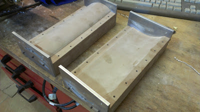
 Both patterns have aluminium side plates to create the verticall wall for the composite tooling. A pair of these plates is used joint the composite tooling for the cure cycle.
The plates also have the drilling guidance holes to drill the CFRP inserts on the actual cured part for mounting onto the endplate.


 This is the impregnated fabric with resin. I used a conventional 2x2T 200gsm with EPOLAM 2022 epoxy resin. The cutting templates are defined in Catia according to the layup sequence and ply contourn. A layer of 80 gsm GF is used on the tooling surface to improve surface finishing.


 This is the fabric being laid-up. It handles well, because it is impregnated feels like a prepreg with a very low resin viscosity. This step is performed on both patterns to obtain the top and bottom wing mould surfaces.

 I made an oven from scratch to cure composite parts, which is really handy. It controls the air temperature only but works wonderfully for such small components. Of course, I use vacuum to compact the parts, as you can tell from the picture.


The mould surfaces are then polished to obtain a better cosmetic finishing on the wing surface. The polishing should be made to 1200 grid.